Protocol Data Types¶
All data is transmitted in a JavaScript* Object Notation (JSON) subset, as described in section §: Message Passing Protocol.
Base Types¶
Numeric Types¶
Numeric types are transmitted as JSON* integers. Numbers are represented in JSON* using the following representation:
| Type | Data Size | JSON* Representation |
|---|---|---|
| Uint8 | 8 bits | 0..255 |
| Uint16 | 16 bits | 0..65535 |
| Uint32 | 32 bits | 0..4294967303 |
The JSON* representation does not indicate the size of the object. The size (8-bits, 16-bits, and 32-bits) is given to allow constrained implementations the ability to select the data size in which to store the result.
Also, there are no negative numbers used in the JSON* subset. The parser does not have to support them.
All integers will fit in 32 bits of data. However, integers in the range of 0x8000000-0xffffffff may be interpreted as negative numbers on some systems (For example, Java* integers). The implementations should take care to ensure that the integers are always treated as positive.
Boolean¶
True is represented as the number 1
False is represented as the number 0
JSON* true and false are not used.
String Types¶
Strings are represented as JSON* strings, delimited with double quotation marks ("). However:
-
Only printable ASCII characters may be in strings (ASCII codes 0x20-0x7e).
-
Non-ASCII characters may be encoded in \uXXXX format (For example, \u20ac is the euro symbol).
-
To simplify parsing, the follow characters may not be encoded in strings, except using the \uXXXX format:
-
Double quote (", \u0022)
-
Open and close square brackets ([, \u005b) and (], \u005d)
-
Open and close brace brackets ({, \u007b) and (}, \u007d)
-
Backslash (\, \u005c)
-
Ampersand (&, \u0026)
-
Backslash escaping is NOT used (For example, a string containing a double quote "\"" must be transmitted as "\u0022" rather than "\"").
ByteArray Types¶
Byte arrays are represented as a string containing base64 data, padded with equal signs. The string may contain only the base64 characters, and may not contain embedded spaces or new lines, regardless of its length. With this proviso, the base64 encoding follows MIME, as described in [[RFC2045]]. However, only characters from the base64 alphabet may be encoded into these strings; whitespace is not permitted.
For example:
" CgU/GQ==" represents a byte array with 4 bytes, containing 10,5,63,25.
Byte arrays look like JSON* strings. The context is used to tell them apart.
The length of a ByteArray is not specified in the encoding, but messages always have a length field sufficient to pre-allocate storage for the ByteArray. This is not needed for the encoding, but makes constrained implementations easier. Note that, if the storage for the ByteArray is n, the length of the base64 string is ((n+2)/3)*4, using integer arithmetic.1
To simplify the parser, we specify that ByteArrays always contain encoded data for every byte (this avoids the need to scan ahead to see how big the input is compared to the expected buffer size).2
Composite Types¶
Composite types are combinations or contextual encodings of base types. In the following table, the type is represented by a JSON* pseudo-code, where name(type) is used to indicate the name of the quantity and the JSON* type.
| Type | Format | Meaning |
|---|---|---|
| Stream Message3 |
|
See section §. The length is stored in hexadecimal format fully specified as 4 hex characters. A message longer than 0xFFFF bytes is stored as a 32-bit hexadecimal number fully specified as 8 hex characters. Implementations should store hex strings using upper case letters. Implementations should parse hex strings whether they have upper case or lower case letters in them. This message header need not be transmitted in some protocols. |
| ProtocolVersion | Integer, represented as: Major * 100 + Minor | States the protocol version. For example: version 10.35 is represented as: 1035. |
| Hash / HMAC |
|
Crypto hash, with length in bytes preceding. For example, a SHA256 hash looks like:
|
| PKNull |
|
Encoding of null public key, used as a placeholder when no public key is available. |
| PKX509Enc |
|
Encoding of Public Key in X.5094 |
| PKRMEEnc |
|
Public Key RSAMODEXP encoding. Encoding is compatible with Java* BigInteger |
| PKEPIDEnc |
|
Public Key EPID 1.1 encoding. The group no identifies the specific Intel® EPID public key used to generate the signature. The actual key value is extracted from Intel® EPID artifacts are maintained by Intel. |
| SigInfo |
|
SigInfo is used to encode parameters for the device attestation signature, This is specifically needed for Intel® EPID revocation and other parameters needed for Intel® EPID signing. sgType is a Signature Type from section § . |
| PublicKey |
|
Public key. Body is one of the above types, depending on the encoding. |
| Signature |
|
The actual signature bits. These come at the end of the signature block. |
| SignatureBlock |
|
|
| ManufacturerBlock |
|
Manufacturer block, stored in device |
| OwnerBlock |
|
Ownership block, stored in device |
| DeviceCredentials |
|
Credentials stored in device |
| Nonce | ByteArray (16 bytes) | 128-bit Random number, intended to be used *only once*. |
| GUID | ByteArray (16 bytes) | 128-bit Random number used for identification. Typically 128 bits. |
| IP Address |
|
Length = 4 for IPv4. Length = 16 for IPv6. |
| RendezvousInstr |
|
Length = num of ve:v pairs. VE6 stands for Variable Encoding. |
| RendezvousInfo |
|
Rendezvous information. This explains how to contact a Rendezvous Server. |
| AppID |
|
AppID values currently in use are allocated by the Intel Client.10 This type value is not currently used, but maintained for backwards compatibility. |
| KeyExchange |
|
Key exchange parameters7 |
| IVData |
|
Cipher Initialization Vector (section §). IV encoded as byte array |
Hash Types and HMAC Types¶
Hash types are based on IANA DNSSEC codes. Please view the following webpage for more details:
http://www.iana.org/assignments/dns-sec-alg-numbers/dns-sec-alg-numbers.xhtml
HMAC types are the corresponding hash type incremented by 100. The HMAC secret must be derived by context.
| Hash number | Hash Algorithm |
|---|---|
| 0 | No hash present or hash/HMAC of illegal length present. This value is used only in the Credential Reuse protocol. |
| 8 | SHA256* |
| 10 | SHA512 |
| 14 | SHA384 |
| 108 | HMAC-SHA256* |
| 110 | HMAC-SHA512 |
| 114 | HMAC-SHA384 |
| Other values | Reserved |
The size of the hash and HMAC functions used in the protocol depend on the size of the keys used for device and owner attestation. Table 3‑4 lists the mapping. The hash and HMAC that are affected by the size of device and owner attestation keys are listed as follows:
-
Hash of device certificate in Ownership Voucher (OP.hdc)
-
Hash of previous entry in Ownership Voucher entries (OP.OwnershipProxyEntry.hp)
-
Hash of header in Ownership Voucher entries (OP.OwnershipProxyEntry.hc)
-
Public key hash in Ownership Credentials (PM.CredOwner.pkh)
-
Hash of to0d object (TO0.OwnerSign.to1d.to0dh)
-
HMAC generated by device (DI.SetHMAC.hmac ,TO2.Done.hmac, and OP.hmac)
| Device Attestation | Owner Attestation | Hash and HMAC Types |
|---|---|---|
| Intel® EPID | RSA2048RESTR | SHA256/HMAC-SHA256 |
| ECDSA NIST P-256 | RSA2048RESTR | SHA256/HMAC-SHA256 |
| ECDSA NIST P-384 | RSA2048RESTR | SHA384/HMAC-SHA384 (Not a recommended configuration)* |
| Intel® EPID | RSA 3072-bit key | SHA256/HMAC-SHA256 |
| ECDSA NIST P-256 | RSA 3072-bit key | SHA256/HMAC-SHA256 (Not a recommended configuration)* |
| ECDSA NIST P-384 | RSA 3072-bit key | SHA384/HMAC-SHA384 |
| Intel® EPID | ECDSA NIST P-256 | SHA256/HMAC-SHA256 |
| ECDSA NIST P-256 | ECDSA NIST P-256 | SHA256/HMAC-SHA256 |
| ECDSA NIST P-384 | ECDSA NIST P-256 | SHA384/HMAC-SHA384 (Not a recommended configuration)* |
| Intel® EPID | ECDSA NIST P-384 | SHA384/HMAC-SHA384 |
| ECDSA NIST P-256 | ECDSA NIST P-384 | SHA384/HMAC-SHA384 (Not a recommended configuration)* |
| ECDSA NIST P-384 | ECDSA NIST P-384 | SHA384/HMAC-SHA384 |
Note on not recommended configurations, above
The Ownership Voucher and the Device key in this configuration have different cryptographic strengths. It is recommended that the strongest cryptographic strength always be used, and that the strengths match between Device and Owner.
Public Key Types¶
Public keys types are based on IANA DNSSEC codes, see:
http://www.iana.org/assignments/dns-sec-alg-numbers/dns-sec-alg-numbers.xhtml
The public key length is derived based on the (explicit) length of the storage provided for it.
| Public Key Number | Public Key Algorithm |
|---|---|
| 0 | No public key present |
| 1 | RSA2048RESTR (RSA with restrictions imposed by legacy TEE environments) |
| 2 | DH |
| 3 | DSA (not currently used) |
| 4 | RSA_UR (Any valid RSA public key) |
| 13 | ECDSA P-256 |
| 14 | ECDSA P-384 |
| 90 | Intel® Enhanced Privacy ID (Intel® EPID) v1.0 |
| 91 | Intel® EPID v1.1 |
| 92 | Intel® EPID v2.0 |
| 113 | ECC P-256 key used for ECDH key exchange (this code is not currently used in the protocol) |
| 114 | ECC P-384 key used for ECDH key exchange (this code is not currently used in the protocol) |
| Other values | Reserved |
Public Key Encodings¶
The key encoding is listed in the table below.
| Public Key Encoding | Encoding Name |
|---|---|
| 0 | No public key present |
| 1 | X.509 |
| 3 | RSAMODEXP – RSA2048RESTR or RSA_UR key with modulus + exponent |
| 4 | Intel® EPID |
Owner and Server implementations must support all public key encodings, as well as null keys under X.509 encoding.
RSAMODEXP Encoding¶
In the RSAMODEXP encoding, an RSA key is represented by two byte arrays, one for the modulus and one for the exponent. The modulus and exponent are based on the Java* Big Integer encoding, a big-endian, signed, two’s complement representation:
-
Big-endian: most significant byte is first, least significant byte is last.
-
Signed encoding: the modulus and exponent are always positive, but the encoding can handle negative numbers. This means that the most significant bit of the most significant byte (that is, the top bit of byte 0) must match the sign. To accomplish this, an extra most significant byte of 0x00 or 0xff might need to be pre-pended to the number. For example: 32768 = 0x8000 must be represented as three bytes: 0x008000. Note that this may require removing the first byte transmitted for some crypto packages and key values.
-
Two’s complement: the normal encoding of integers in a computer, where the negative of a number is the complement of the bits (aka: one’s complement), plus one. For example, 32768 is represented as: 0x008000 (as above). Complementing the bits gives 0xff7fff. Adding one gives: 0xff8000 which is -32768. This can be simplified to two bytes: 0x8000, since the sign bit still correctly identifies the number as negative.
-
For implementation, we are aware of crypto packages that use similar encodings, except that the modulus and exponent are always positive, so no extra sign byte is needed. The above encoding may need to be “tweaked” by removing/adding the extra sign byte to work with such packages. For example, one package requires that the size of the modulus always be the number of bytes which is a power of two (For example, 256 bytes), and the sign byte pushed it over by one (to 257 bytes).
Signatures¶
A signature is a JSON* object with 3 tags:
-
"bo" -- the body to be signed. The signature body is the entire object associated with the “bo” tag, exclusive of the tag itself. This object is hashed byte-for-byte as transmitted. Note that no spaces or comments are permitted in our subset of JSON*, and that strings are always encapsulated with double quotes. In some implementations, it might be necessary to reconstruct the original JSON* from a parsed version to verify the signature.'
-
"pk" -- the public key to apply to the signature. Note, when the Public Key is null, the “pk” tag must still be present with the value “PKNull” (see section §).
-
"sg" -- the signature material itself.
Signatures may be:
-
RSA sign with PKCS1 v1.5 padding, using SHA-256 hash
-
ECDSA NIST P-256. The signature format uses ASN.1 schema ([12], [13]) encoded with Distinguished Encoding Rules (DER) [14].
-
RSA sign with PKCS1 v1.5 padding, using SHA-384 hash (future crypto)
-
ECDSA NIST P-384 (future crypto)
-
Intel® EPID 1.0 signatures. The signature format uses ASN.1 schema ([12], [13]) encoded with Distinguished Encoding Rules (DER) [14]
-
Intel® EPID 1.1 signatures
-
Intel® EPID 2.0 signatures
Signature generation proceeds as follows:
-
Compute the hash on the body, exactly as you will transmit it.
-
Encrypt the hash using the private key.
-
Include the public key in the signature object, under the “pk” tag.
Signature verification proceeds as follows:
-
Compute the hash on the body, exactly as transmitted.
-
Decrypt the signature with the public key, as provided in the “pk” tag.
-
Verify that the decrypted signature matches the hash.
The body is a single JSON* item that is terminated by a comma, which in practice is always a JSON* object. Thus, the plain text for the signature will be an object that is inclusive of the brace brackets.
Example:
{"bo":{"n3":"WpTgdZooMD0="},"pk":[1,3,[257,"AKgIjL … 257 bytes of b64 ...5nCQRk=", 3,"AQAB"]],"sg":[256,"kuL2 ... 256 bytes of b64 … Ps/pfw=="]}
The plaintext to be signed is the string:
{"n3":"WpTgdZooMD0="}
Device Attestation Signature and Mechanism¶
The Device Attestation signature is used by the Secure Device Onboard Device to prove its authenticity to the Secure Device Onboard Rendezvous and the Secure Device Onboard Owner. Various cryptographic signing mechanisms can be used for this purpose. In this specification, we present mechanisms based on Intel® Enhanced Privacy Identifier (Intel® EPID) signatures and Elliptical Curve Digital Signature Algorithm (ECDSA) signatures.
In some cases, a signature cannot stand alone, but requires some protocol interaction to prepare for it. For example, a multi-application Trusted Execution Environment (TEE) may need to negotiate program instance parameters with the verifier before the signature can be trusted. In particular, Intel® EPID signers need to obtain revocation information and cooperatively sign “proofs”. For this reason, the Device Attestation mechanism exchanges the following three messages:
-
eA -- from device to signature verifier, provides initial device based information
-
eB -- from verifier to device, provides a response to eA
-
sg -- from device to verifier, contains the actual signature
The eA and eB messages are structured as “SigInfo”, and contain a field that identifies the signature type as defined in Table 3‑7.
| Encoding | Type Name | Type Description |
|---|---|---|
| 13 | ECDSA P-256 | ECDSA P-256 signature with SHA-256 hash |
| 14 | ECDSA P-384 | ECDSA P-384 signature with SHA-384 hash |
| 90 | EPID10 | Intel® EPID 1.0 signature information for the Intel Client environment. Sufficient information to generate the Intel Client “EPID provisioning” call. |
| 91 | EPID11 | Intel® EPID 1.1 signature information for the Intel Client environment. Sufficient information to generate the Client “EPID provisioning” call. |
| 92 | EPID20 | Intel® EPID 2.0 signature information for non-Intel Client implementation. |
Intel® Enhanced Privacy ID (Intel® EPID) Signatures Overview¶
Intel® Enhanced Privacy ID (Intel® EPID) signatures are generated by Devices that support a Hardware Root of Trust based on Intel® EPID 1.0, Intel® EPID 1.1, or Intel® EPID 2.0.
- Intel® EPID 2.0 is implemented at Intel with both 32-bit and 128-bit group IDs. This specification assumes 128-bit group IDs for Intel® EPID. Intel® EPID 32-bit group IDs are supported by extending the 32-bit group ID to 128 bits by zero padding to the left (most significant bits), thus mapping the 32-bit group space into the 128-bit group space. In some cases, the Secure Device Onboard implementation must convert group IDs back and forth for platform software that requires 32-bit group IDs. To our knowledge, platforms where the Intel® EPID 2.0 software supports only 32-bit group IDs are matched by hardware provisioned with Intel® EPID keys with 32-bits.
The EPID signer needs Intel® EPID revocation information in order to generate a valid Intel® EPID signature from an Intel® EPID private key. In particular, the signer needs the signature revocation list (SIGRL) for its group. The SIGRL may be obtained from Intel’s iKGF web sites, but it is easiest to obtain using the Intel® EPID Verification Service.
In some platforms, Intel® EPID revocation information is downloaded using other tools. However, for consistency, Secure Device Onboard allows the Device to download this information as part of the TO1 and TO2 Protocols.
Intel® EPID information is encoded in the SigInfo structures eA, eB, and in the pkType and sg fields of the signature itself. Typically eA and eB are in subsequent messages, with the Intel® EPID signed message coming just afterwards.
Intel® Enhanced Privacy ID (Intel® EPID) 1.1 Signatures (type EPID11)¶
Intel® EPID 1.1 signature information is encoded using the EPID11 signature type, using the “eA”, “eB” and “sg” fields, each from separate messages. The contents of each field is as follows:
- eA encodes the EPID group ID as 4 bytes, in network byte order (MSB first):
| Type | Name | Description |
|---|---|---|
| BYTE[4] | groupId | EPID 1.1 group ID |
- eB encodes the EPID certificate and other items needed by the Intel Client. The SIGRL is inside the group certificate. Length values (UInt16) are encoded in network order (MSB first):
| Type | Name | Description |
|---|---|---|
| UInt16 | groupCertSigma10Size | Size of data in groupCertSigma10 field |
| BYTE[] | groupCertSigma10 | Legacy group certificate (binary format) |
| UInt16 | groupCertSigma11Size | Size of data in groupCertSigma11 field |
| BYTE[] | groupCertSigma11 | X.509 group certificate |
| UInt16 | sigRLSize | Size of data in sigRL field (in bytes) |
| BYTE[] | sigRL | SigRL as given below |
- If there is no SIGRL, sigRLSize is zero, and sigRL is empty (not present).
Note
sigRL non-zero implies that n2 > 0 (below).
- The sigRL format is as follows (all fields are encoded in network order (MSB first)):
| Type | Field Name | Description |
|---|---|---|
| UInt16 | sver | Intel® EPID version number. Must be 0x0001 for Intel® EPID1.1 |
| UInt16 | blobID | ID of the data type. Must be 0x000e for SigRL |
| UInt32 | gid | Group ID |
| UInt32 | RLver | Revocation list version number |
| UInt32 | n2 | Number of entries in SigRL |
| BYTE[64] (n2 of them) | B[i] for i in range [0; n2-1] | Bi elements of G3 |
| BYTE[64] (n2 of them) | K[i] for i in range [0; n2-1] | Ki elements of G3 |
| BYTE[64] | sig | 512-bit ECDSA signature on the revocation list signed by the issuer using Intel Signing Key (ISK). **Contact Secure Device Onboard Enablement team for details.** |
- sg encodes the signature, according to the Intel® EPID1.1 specification. The length is given in the message format:
| Type | Name | Description |
|---|---|---|
| BYTE[] | signature | Intel® EPID 1.1 signature according to the Intel® EPID 1.1 specification |
The data being signed is:
| Type | Name | Description |
|---|---|---|
| BYTE[48] | Prefix | All zeros, except: Prefix[4]=0x48 and Prefix[8]=0x8 |
| BYTE[16] | ID | App-ID, same as in message body (“ai” tag in messages: TO1.ProveToSDO and TO2.ProveDevice) |
| BYTE[16] | Zero-padding | Zeros |
| BYTE[16] | Nonce | Nonce value same as in message body (“n4” tag in messages: TO1.ProveToSDO and “n6” tag in TO2.ProveDevice) |
| BYTE[16] | Zero-padding | Zeros (used to allow Nonce to be 32 bytes) |
| BYTE[] | Message body | As in this protocol specification, from open to close brace bracket of JSON* text. |
- Rendezvous Service and Owner must (logically) prefix the contents of the message with specific data (as above), before doing Intel® EPID verification.
Intel® Enhanced Privacy ID (Intel® EPID) 2.0 Signatures (non-Intel Client, type EPID20)¶
Intel® EPID 2.0 signatures are encoded using “eA”, “eB” and the “sg” fields, each from separate messages. The contents of each field is as follows:
- eA encodes the EPID group ID as 16 bytes, in network byte order (MSB first). Hosts which use Intel® EPID2.0 with 32-bit group IDs must zero pad the top 96 bits.
| Type | Name | Description |
|---|---|---|
| BYTE[16] | groupId | Intel® EPID 2.0 group ID |
- eB encodes the signature revocation list (sigRL) and EPID group public key. Length values (UInt16) are encoded in network order (MSB first):
| Type | Name | Description |
|---|---|---|
| UInt16 | sigRLSize | Size of data in sigRL field |
| BYTE[sigRLSize] | sigRL | SigRL according to Intel® EPID 2.0 specification |
| UInt16 | publicKeySize | Size of data in publicKey field |
| BYTE[publicKeySize] | publicKey | Group public key according to Intel® EPID 2.0 specification |
- sg encodes the signature, according to the Intel® EPID 2.0 specification. The length is given in the message format.
| Type | Name | Description |
|---|---|---|
| BYTE[] | signature | Intel® EPID 2.0 signature according to Intel® EPID 2.0 specification |
Intel® Enhanced Privacy ID (Intel® EPID) 1.0 Signatures (type EPID10)¶
Intel® EPID 1.0 signature information is encoded using the EPID10 signature type, using the “eA”, “eB” and “sg” fields, each from separate messages. The contents of each field is as follows:
- eA encodes the EPID group ID as 4 bytes, in network byte order (MSB first):
| Type | Name | Description |
|---|---|---|
| BYTE[4] | groupId | Intel® EPID 1.0 group ID |
- eB encodes the Intel® EPID certificate and other items needed by the Intel Client. The SIGRL is inside the group certificate. Length values (UInt16) are encoded in network order (MSB first):
| Type | Name | Description |
|---|---|---|
| UInt16 | groupCertSigma10Size | Size of data in groupCertSigma10 field |
| BYTE[] | groupCertSigma10 | Legacy group certificate (binary format) |
- sg encodes the signature, according to the Intel® EPID 1.0 specification. The length is given in the message format:
| Type | Name | Description |
|---|---|---|
| BYTE[] | Signature | Intel® EPID 1.0 signature according to Intel® EPID 1.0 specification |
The data being signed is:
| Type | Name | Description |
|---|---|---|
| BYTE | ID-length | Length of ID field |
| BYTE[] | ID | App-ID, same as in message body (“ai” tag in messages: TO1.ProveToSDO and TO2.ProveDevice) |
| BYTE[16] | Nonce | Nonce value same as in message body (“n4” tag in messages: TO1.ProveToSDO and “n6” tag in TO2.ProveDevice) |
| BYTE[] | Message body | As in this protocol specification, from open to close brace bracket of JSON text. |
- Rendezvous Service and Owner must (logically) prefix the contents of the message with specific data (as above), before doing Intel® EPID verification.
ECDSA NIST P-256 and ECDSA NIST P-384 Signatures¶
The ECDSA attestation is used for devices where the Intel® EPID privacy mechanisms are not needed. The Device contains an ECDSA private key, and the Ownership Voucher is enhanced to give the Owner access to the public key. The public key is typically encoded in an X.509 certificate, signed by one or more Certificate Authorities. The private key is used to sign the device attestation. The public key is used to verify the signature.
For ECDSA attestation, the Length field in eA and eB encoding is set to 0 and Info field is not present (zero length). ECDSA NIST P-256 uses SHA-256 hash, and ECDSA NIST P-384 uses SHA-384 hash.
For ECDSA, both the private key and the public key are Device identities. This means that the Secure Device Onboard Rendezvous Service and Secure Device Onboard Owner who verify the Device attestation signature receive a unique and permanent identity for the device, even before they verify the signature. This information can be used to trace the subsequent owners of the device. For this reason, we recommend careful administrative measures to ensure that this information is used securely and discarded appropriately.
Null Public Keys¶
A public key in the “pk” tag may be left as null. This is done when the public key is already known to the verifying party, because it is a requirement that it know it, or because it was already transmitted earlier.
Intel® EPID public keys encode only the group number in the “pk” tag, since this is sufficient to identify the public key to the Intel back end.
Null public keys are used for some testing stubs.
RendezvousInfo¶
The RendezvousInfo type indicates the manner and order in which the Device and Owner find the Rendezvous Server. It is configured during manufacturing (For example, at an ODM), so the manufacturing entity has the choice of which Rendezvous Server to use and how to access it.
RendezvousInfo consists of a sequence of rendezvous instructions which are interpreted in order during the TO0 and TO1 Protocols (JSON* sequence of object, such as [{t1:v1,…},…,{tn,…}]). The tags are encoded in alphabetical/character encoding order.
Unlike other Secure Device Onboard JSON* objects, JSON* tags appear only for instructions that differ from the default. Other variables assume default values. A default value of “none” indicates that the variable is assumed not present in the instruction unless its tag appears explicitly.
Each set of rendezvous instructions (that is, each element of the JSON* sequence) is interpreted as one set of instructions for reaching the Rendezvous Server, with differing conditions. For example, one set might indicate using the wireless interface, and another set might indicate using the wired interface. It is possible that a given set corresponds to multiple ways to access the Rendezvous Server (For example, multiple IP addresses that correspond to a single DNS name), and these must all be tried before the Device or Owner moves to the next element of the sequence.
The Owner and Device process the RendezvousInfo, attempting to access the Rendezvous Server. The first successful connection may be used.
The Device and Owner may avoid obviously redundant operations, such as contacting the same IP address twice when a DNS name maps to an IP address explicit in a separate rendezvous instruction.
To execute each rendezvous instruction, the program defines a set of variables, one for each JSON* tag in the RendezvousInfo instructions. It initializes all variables to default values. Then the rendezvous instruction is interpreted, and updates each variable. If the user input variable is set to true, and user input is available, the user is allowed to update each variable. On constrained devices, some variables do not exist. The constrained implementation interprets each instruction as if this variable was not present.
Some variables apply only to the Owner and some only to the Device. See the table below. When a variable does not apply, it is interpreted as if it had never been specified. This means that the Owner can only ever notice the tags: “only”, “ip”, “pow”, “delaysec”, and “dn”. This is because the Owner, as a cloud-based server, is expected to use normal Internet rules to access the Rendezvous Service. The Device, which may be in a specialized network and may be constrained, might need additional parameters.
The “only” (Only for) and "delaysec" tags have side effects.
-
When "only":"dev" appears in a set of instructions, an Owner must skip the entire set
-
When "only":"owner" appears in a set of instructions, a Device must skip the entire set
-
When "delay":UInt32 appears in a set of instructions, the set is followed by a delay for the number of seconds specified, increased or decreased by a random value up to 25%. An instruction that contains just a “delay”, can be appended to the end of the RendezvousInfo to force a particular randomized delay before retrying the entire sequence.
| Rendezvous Instruction Variable | Default Value | Variable Encoding Tag | Variable Type | Required | Device | Owner |
|---|---|---|---|---|---|---|
| Only for | None | "only" | "dev" or "owner" | No | Yes | Yes |
| IP address | None | "ip" | IPAddress | Yes | Yes | Yes |
| Port, Device | Based on protocol | "po" | UInt16 | Yes | Yes | No |
| Port, Owner | Based on protocol | “pow” | UInt16 | No | No | Yes |
| DNS name | None | "dn" | String | Yes | Yes | Yes |
| TLS Server cert hash | None | "sch" | Hash | No | Yes | No |
| TLS CA cert hash | None | "cch" | Hash | No | Yes | No |
| User input | No | "ui" | UInt8 (0/1) | No | Yes | No |
| SSID | None | "ss" | String | If has Wi-Fi* | Yes | No |
| Wireless Password | None | "pw" | String | If has Wi-Fi* | Yes | No |
| Wireless Security Password | Chosen Automatically | "wsp" | String | If has Wi-Fi* | Yes | No |
| Medium | *Device dependent* | "me" | String | Yes | Yes | No |
| Protocol | TLS | "pr" | String | No | Yes | No |
| Delay | 0 | “delaysec” | UInt32 | Yes | Yes | Yes |
Rendezvous Instruction (RendezvousInstr) entries are specified as having the variables in alphabetical order. This does not affect the interpretation of these variables, but makes the computation of a signature that includes them simpler for some implementations.
-
If the “only” element appears, and the value does not match the interpreting entity (Device/Owner), this instruction is terminated and control proceeds with the next set of instructions.
-
Medium is selected (“me”). The Device uses the selected preferred medium, or terminates this instruction. When no medium is specified, the Device may establish its own preference, perhaps based on the other parameters (for example, TLS might be available on one medium, but not another).
-
The protocol is chosen (“pr”), if it is supported. Otherwise, the instruction terminates. The Owner always chooses the protocol “https”.
-
The Device attempts to resolve the DNS address. If DNS query is successful, then the resolved IP addresses are tried one after another.
-
Else, if DNS resolution fails or the Device fails to communicate with all of the resolved IP addresses, then the specified IP address is used as the target IP address.
-
Else, the instruction terminates.
-
If TLS is used on a Device (pr=https or pr=tls), the hash instructions are used as specified against server certificates appearing in the TLS handshake (or, for ps=https, the underlying TLS connection’s handshake). This applies to the Device only.
-
If the server certificate hash is specified (on a Device), the server’s certificate is extracted from the certificate chain, SHA256 hash computed, and compared to the specified value. Failure to match causes the TLS authentication to fail.
-
If the CA certificate hash is specified (on a Device), the other certificates in the server certificate chain are extracted one by one, SHA256 hash computed, and compared to the specified value. Any match allows TLS authentication to proceed. No match causes TLS authentication to fail.
-
The Owner always applies usual CA trust to server certificates used in TLS for the TO0 Protocol.
-
Attempt as many connections as are implied by the set of variables established and choices made, above. For example, try each of the addresses returned by a DNS query if there is a valid DNS name.
-
If a “delaysec” tag appears, delay as specified.
-
If “delaysec” does not appear and the last entry in RendezvousInfo has been processed, a delay of 120s ± random(30) is executed.
Medium values:
| "eth0".."eth9" | mapped to first through 10th wired Ethernet interfaces. These interfaces may appear with different names in a given platform. |
| "eth\*" | means to try as many wired interfaces as makes sense for this platform, in any order. For example, a device which has one or more wired interfaces that are configured to access the Internet (For example, “wan0”) might use this configuration to try any of them that has Ethernet link. |
| "wifi0" .. "wifi9" | mapped to first through 10th Wi-Fi* interfaces. These interfaces may appear with different names in a given platform. |
| "wifi\*" | means to try as many Wi-Fi* interfaces as makes sense for this platform, in any order |
| *Others* | *device dependent.* |
Protocol Values:
| "rest": |
first supported protocol from:
|
| "tcp": | bare TCP, if supported |
| "tls": | bare TLS, if supported |
| "CoAP/tcp": | CoAP protocol over tcp, if supported |
| "http": | HTTP over TCP |
| "https": | HTTP over TLS, if supported |
Example of RendezvousInfo: Different Ports for Device and Owner¶
…"r":[1,{"dn":"mpservice.net","po":80,"pow":443}]…
On both Device (TO1 Protocol) and Owner (TO0 Protocol), attempt to connect to all IP addresses returned by the DNS query for “mpservice.net”. The Owner queries TO0 Protocol on port 443 (Owner always uses TLS). The Device queries TO1 Protocol on port 80 (might be HTTP or HTTPS, or both, depending on the device default).
In the following situation, the Device needs to try Wi-Fi* media, as many as it can connect to. The Owner just uses the DNS name without the Wi-Fi* media specification, because “me” applies only to Devices, and is thus ignored by the Owner.
[1,{"me":"wifi\*","dn":"mpservice.net"}]
The above is thus equivalent to:
[2,[3, {"only":"dev","me":"wifi\*","dn":"mpservice.net"}],
   [2{"only":"owner","dn":"mpservice.net"}]]
(Inserted newline for formatting purposes)
In the above, “eth” could be used for wired interfaces that are purposed for Internet access, such as the outside* wired interface on a gateway or router.
ServiceInfo and Management Service – Agent Interactions¶
The ServiceInfo type is a collection of key-value pairs which allows an interaction between the Management Service (on the cloud side) and Management Agent functions (on the device side), using the Secure Device Onboard encrypted channel as a transport.
Conceptually, each key-value pair is a message between a module in the Owner and a module on the Device that implements some primitive function. Messages have a name and a value. The ServiceInfo key is the module name and the message name, separated by a colon. ServiceInfo is constrained to a subset of printable ASCII, but base64 or other encoding may be used to encode any textual or binary formats.
| ServiceInfo Key | ServiceInfo Value |
|---|---|
| moduleName:messageName where both moduleName and messageName are printable ASCII characters containing no Unicode escapes (\uXXXX) or the characters: {}[]&"\ (see Table 1 in section §). Where appropriate, the moduleName may contain a version of the module. By convention, the version is separated using a hyphen character (‘-‘), as in: tpm-1.2 or tpm-2. | Printable ASCII characters containing no Unicode escapes (\uXXXX) or the characters: {}[]&"\ (see Table 1 in section §) Individual or lists of Numbers and selectors (enum type strings) may be expressed directly in ASCII. Textual and binary data should be encoded in base64. Other encodings are permissible on a module-by-module basis, with the above limits. |
Messages sent to a module on the Secure Device Onboard Device may interact with the Device OS to install software components. Another message might use those components in combination with a cryptographic key, to establish communications. In some systems, the Management Agent might be installed by cooperating modules before it is active by others, allowing an “off-the-shelf” device to be customized by Secure Device Onboard.
The intention is that modules will implement common or standardized IOT provisioning functions, and will be reused for different IOT solutions provisioned by Secure Device Onboard.
In some cases, modules on the Secure Device Onboard Owner and Secure Device Onboard Device will be designed to cooperate directly with each other. For example, a module that implements a particular device management client on the Secure Device Onboard Device, and its counterpart that feeds it exactly the right credentials on the Secure Device Onboard Owner. In other cases, modules may implement IOT or OS primitives so that the Secure Device Onboard Owner or Secure Device Onboard Device picks and chooses among them. For example, allocating a key pair on the Secure Device Onboard Device; signing a certificate on the Secure Device Onboard Owner; transferring a file into the OS; upgrading software; and so on.
The following set of examples is presented for illustrative purposes, and is not intended to constrain Secure Device Onboard implementations in any way:
| Example Key | Example Value | Comment |
|---|---|---|
| firmware_update:active | 1 | Hypothetical firmware update module, sends “active” message with value of 1 (true) |
| firmware_update:codeSize | 262144 | Code size is 256k |
| firmware_update:code001 | Base64 data | First 512 bytes of firmware update, encoded in base64 |
| firmware_update:verify | Base64 data | SHA-384 of firmware image |
| wget:hashSha384 | Base64 data | SHA-384 hash of data that is downloaded in the next message |
| wget:CAfiles.dat | http://myserver/CAfiles.dat | Download CA database |
| cmd-linux:\#!/bin/sh | exec /usr/local/bin/mydaemon -k mykeyfile.pkcs7 -ca CAfiles.dat | Hypothetical module to execute Linux* scripting commands, message name gives interpreter, value gives shell code |
The API between the Management Agent / Device OS and the Secure Device Onboard Device, and between the Management Service and the Secure Device Onboard Owner, are outside the scope of this document. The requirements for this API are as follows:
-
A mechanism to discover modules on the Secure Device Onboard Owner and to establish a preference among them (analogous to a preference for TPM2 over TPM1.2)
-
A mechanism to connect modules on the Secure Device Onboard Device. A complex Secure Device Onboard Device might be able to discover modules, but a simpler device could have modules “hard” coded
-
A mechanism to generate Secure Device Onboard messages to modules. As above, modules can send messages to their counterparts or to other modules
-
On constrained Secure Device Onboard Devices, common code for performing base64 decoding is desirable.
Common code for modules to store and buffer state from messages is desirable.
On complex Secure Device Onboard Devices, the ability of modules to send messages to each other may also be supported. For example, a file transfer module and a file storage module might be called as primitives for a “file transfer and store” module.
One special case of the above. We envision a “TEE” module, that encapsulates messages for other modules, but causes an error unless these modules are implemented at the same security level as the Secure Device Onboard implementation (For example, in the same Trusted Execution Environment). For example, TEE:tpm:createkey causes an error if the module called “tpm” is not at the same security level as Secure Device Onboard. This module might encrypt data to ensure that it can only be processed in a trusted environment. Implementations which support multiple security levels for code execution should allow for this function, since this capability cannot be simulated using other Secure Device Onboard mechanisms.
Mapping Messages to ServiceInfo¶
A module may have an arbitrary number of messages. There are no arrays, but numbered message names can be used to simulate their effect (mod:key1, mod:key2).
Since ServiceInfo messages are separated into one or more Secure Device Onboard messages, it is possible to use the same message over and over again. Whether this is has a cumulative or repetitive effect is up to the module that interprets the messages (For example, file:part might be repeated for successive parts, but tpm:certificate might be individual certificates).
Messages are processed in the order they appear in ServiceInfo.
The same message may also be repeated in a single ServiceInfo.
ServiceInfo does not have to be interpreted as it is parsed from the message. It is legal to buffer the entire ServiceInfo and interpret it all later. However, the messages must be interpreted in the same order.
The SDO Device Module¶
The “sdodev” module implements a set of messages to the Secure Device Onboard Owner that identify the capabilities of the device. All Secure Device Onboard Owners must implement this module, and Secure Device Onboard Owner implementations must provide these messages to any module asks for them. The “sdodev” messages must appear first in the Device ServiceInfo.
The following messages are defined in the SDO Device Module:
| Device Service Info Key | Disposition | Meaning / Action |
|---|---|---|
| sdodev:os | Required | OS name (For example, Linux*) |
| sdodev:arch | Required | Architecture name / instruction set (For example, X86_64) |
| sdodev:version | Required | Version of OS (For example, “Ubuntu* 16.0.4LTS”) |
| sdodev:device | Required | Model specifier for this Secure Device Onboard Device, manufacturer specific |
| sdodev:sn | Optional | Serial number for this Secure Device Onboard Device, manufacturer specific |
| sdodev:pathsep | Optional | Filename path separator, between the directory and sub-directory (For example, ‘/’ or ‘\’) |
| sdodev:sep | Required | Filename separator, that works to make lists of file names (For example, ‘:’ or ‘;’) |
| sdodev:nl | Optional | Newline sequence (For example, “\u000a” or “\u000d\u000a”) |
| sdodev:tmp | Optional | Location of temporary directory, including terminating file separator (For example, “/tmp”) |
| sdodev:dir | Optional | Location of suggested installation directory, including terminating file separator (For example, “.” or “/home/sdo” or “c:\Program Files\SDO”) |
| sdodev:progenv | Optional | Programming environment. See Table 22 |
| (For example, “bin:java:py3:py2”) | ||
| sdodev:bin | Required | Either the same value as “arch”, or a list of machine formats that can be interpreted by this device, in preference order, separated by the “sep” value |
| (For example, “x86:X86_64”) | ||
| sdodev:mudurl | Optional | URL for the Manufacturer Usage Description file that relates to this device (See CR023) |
| sdodev:modules | Optional | A list of module names supported by this Secure Device Onboard Device, separated by the separator specified in “sdodev:sep” |
The “progenv” key-value is used to indicate the Device’ capabilities for running programs. This is a list of tags, separated by the “sep” value, that indicates which programming environments are available and preferred on this platform. For example, bin;perl;cmd means use system binary format (preferred), but Perl* is also supported, and Windows* CMD shell is also supported, but Perl* is preferred over CMD.
The following tags are supported at present. Version numbers may be appended to the tag (as in py2 and py3).
| “progenv” tag | Meaning |
|---|---|
| bin | System-dependent most common binary format (the “arch” key-value may inform the format) |
| java | Java* class/jar (openJDK* compatible) |
| js | Node.js* (Javascript*) |
| py2 | Python* version 2 |
| py3 | Python* version 3 |
| perl* | Perl* 5 |
| bash | Bourne shell |
| ksh | KornShell* |
| sh | *NIX system shell (whichever one it is) |
| cmd | Windows* CMD |
| psh | Windows PowerShell* |
| vbs | Windows Visual Basic* Script |
| … | (Other specifiers may be defined on request. Contact the Secure Device Onboard Enablement team) |
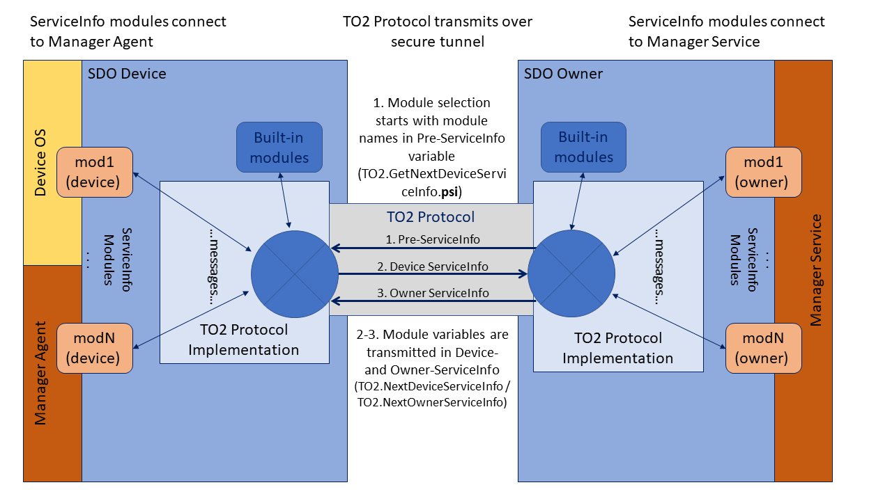
Module Selection¶
In some Secure Device Onboard implementations, multiple modules can perform overlapping functions. Some modules may implement legacy versions of others (For example, TPM versions) and some modules may implement alternative IOT control techniques (For example, MQTT versus CoAP). The Secure Device Onboard Owner and Secure Device Onboard Device need to negotiate to select the right set of modules.
In this version of Secure Device Onboard, module selection is as follows:
-
The [TO2.GetNextDeviceServiceInfo.psi]
variable lists modules supported by the Secure Device Onboard Owner in order of Owner preference. -
The [Device ServiceInfo] indicates which modules are selected by including an “active” message and provides device-side data for the modules from the Management Agent.
-
The [Owner ServiceInfo] may deselect modules with its own “active” messages, and provides messages containing owner-side data from the Management Service.
If possible, all module functions should complete in time to allow the Secure Device Onboard operation to succeed or fail based on module operation, so that a module failure causes the entire Secure Device Onboard operation to fail and be retried later. In some cases, the module cannot determine success criteria before Secure Device Onboard completes (For example, a firmware update module must restart the system to invoke the new software), and Secure Device Onboard must complete “on faith” that all is well.
Any error in a module must cause the entire Secure Device Onboard session to fail with an error message.
Module Selection Using the Pre-ServiceInfo (PSI) Variable11¶
The “Pre-ServiceInfo” variable: TO2.GetNextDeviceServiceInfo.psi is a string that starts the ServiceInfo handshake. The Psi variable encodes a mini-ServiceInfo. The format of the “psi” variable is:
modName1 : modMsg1 \~ modVal1 , modName2 : modMsg2 \~ modVal2 …
This is a comma-list of module-message-value triplets, where the module name is delimited with a colon (‘:’), and the message is delimited from the value with a tilde (‘\~’).
The moduleData is used when the Secure Device Onboard Device must perform specific Owner-driven operations before the Device ServiceInfo. For example, a TPM module might need the number of key pairs to allocate.
The purpose of the Pre-ServiceInfo (PSI) variable is to allow the Secure Device Onboard Owner to require specific action from the Secure Device Onboard Device before it sends the Device ServiceInfo. This might be required, for example, if the Secure Device Onboard Owner needed the Secure Device Onboard Device to allocate a specific number of keys or other resources, then offer them to the Secure Device Onboard Owner. This choice might imply a preference from the Owner to the Device as well.
If the Secure Device Onboard Owner has no such requirement, it need not generate the Pre-ServiceInfo. For example, a constrained Secure Device Onboard Device may always generate the same Device ServiceInfo. In this case, the Pre-ServiceInfo has no function.
Module information in the PSI may be used to indicate a preference for one module over another. For example, the Secure Device Onboard Owner may indicate that a TPM2 module is preferred over a TPM1.2 module, even if both are supported by the Owner and the Device.
Consider the following psi variable:
tpm-1.2:pref\~tpm-2;tpm-2:keys\~3,tpm-2:type\~ecc,
tpm-1.2:keys\~3,tpm-1.2:type\~rsa
This might indicate support for: a tpm module at version 2 that has an argument indicating 3 RSA key-pairs are needed, the same module at version 1.2 also needing 3 key-pairs (but ECC); and a preference for module tpm-2 over tpm-1.2 (the “pref” message).
Following this example, an Secure Device Onboard Device that supports TPM 1.2 can enable the appropriate module and allocate 3 RSA key pairs, and another Secure Device Onboard Device with both TPM 1.2 and TPM 2.0 capability can select TPM 2.0 and allocate 3 ECC key pairs. In each case, the Device ServiceInfo is used to activate a particular module.
Constrained Secure Device Onboard implementations do not need to parse Pre-ServiceInfo, unless they need to access moduleData. Specifically, a constrained Secure Device Onboard Device that always allocates one key pair does not need to scan the “psi” variable.
Module Activation in Device ServiceInfo¶
A module on the Secure Device Onboard Device indicates its availability to the Secure Device Onboard Owner by sending the active message with value 1 (true):
In Device ServiceInfo: … "modName:active":"1", …
The active message must precede all other messages sent by a given module.
An Secure Device Onboard Owner may only send messages to a module that has sent an active message. Messages to non-existent or non-activated modules cause the Secure Device Onboard session to be terminated with an error message.
An Secure Device Onboard Owner may refuse the activation of a module by sending a de-activating active message:
In Owner ServiceInfo: … "modName:active":"0", …
If the Secure Device Onboard Owner sends a de-activate message, it may not send any other messages to this module in this Secure Device Onboard session. The Secure Device Onboard Owner must de-activate all modules that it does not intend to use.
For example, a constrained Secure Device Onboard Device may implement a management module and a firmware update module. It activates both modules, sending the current firmware version as a parameter of firmware update. The Secure Device Onboard Owner can decide either to accept this version of firmware and de-activate the firmware update module, or decide to update the firmware and de-activate the management module.
Secure Device Onboard Version 1.0 Key-Values¶
Version 1.0 of Secure Device Onboard implemented a different set of key-value pairs. We have elected to replace this mechanism with the current one.
Implementers who need to support the previous Device- and Owner-ServiceInfo key-value pairs should contact the Secure Device Onboard Enablement team at Intel.
Examples¶
In the following examples, spaces are provided for clarity, and fragments of ServiceInfo are presented.
Expressing Values in Different Encodings¶
… "mymod:options","foo,bar"…
… "mymod:options","Zm9v,YmFy" …
… "mymod:options","Zm9vLGJhcg==" …
These 3 example each defines a message “options” with value “foo,bar”. The first gives the value in printable ASCII, the second in a list of base64 values, the third as a list completely encoded in base64.
Which value is correct depends on the implementation of “mymod”.
Hypothetical File transfer (Owner ServiceInfo)¶
"binaryfile:name","myfile.tmp",
"binaryfile:length","1234",
"binaryfile:data001","—base64-data-512-bytes—",
"binaryfile:data002","—base64-data—512-bytes—",
"binaryfile:data003","—base64-data-210-bytes—",
"binaryfile:sha-384","—base64-data—48-bytes—"
In this example, a “binary file” module allows a file to be downloaded using the Secure Device Onboard secure channel. The data002 and data003 variables need to be in separate ServiceInfo messages to keep message sizes within spec. Base64 encoding is used to allow the module to generate a binary file. The last message allows the file transfer to be verified after it is stored in the filesystem, as an added integrity check.
Another way to accomplish file transfer would be to use an external HTTP connection. For example:
"wget:filename":"myfile.tmp",
"wget:url":"http://myhost/myfile.tmp",
"wget:sha-384":"—base64-data—48-bytes—"
In this case, the file is transferred using a separate connection, perhaps at OS level. If the file is confidential, ‘https:’ could be used instead of ‘http:’.
Both these techniques are valid in Secure Device Onboard, and represent two sides of a trade-off. Using the Secure Device Onboard channel, a small file can be transferred without needing a parallel network connection (see section § for limitations on the Secure Device Onboard channel size). However, the same file might be transferred much faster using an optimized HTTP implementation, and might not require the confidentiality built into Secure Device Onboard (For example, the file contents might be posted on a public Internet site). Table 23 discusses the trade-off.
Secure Device Onboard is tuned to provide access to the Secure Device Onboard server using HTTP or HTTPS. Since Secure Device Onboard may run in a proxy environment created by the Secure Device Onboard Installer Tool (see section §), other protocols should be used only when both the Secure Device Onboard Device, Secure Device Onboard Owner and the installation network are known to support them. Otherwise, stick with HTTP/HTTPS.
| File Transfer Using Secure Device Onboard Channel | File Transfer Using HTTP Mechanism |
|---|---|
| Performance based on Secure Device Onboard protocol (slow for file large data) | Performance based on HTTP or HTTPS, designed for streaming large amounts of data. Second stream required. |
| Can download large amounts of bulk data or programs (limited to the number of ServiceInfo iterations) | Can download arbitrary amounts of bulk data or programs |
| Data can be stored in a file | Data can be stored in a file |
| Data can be executed as a program | Data can be executed as a program |
| Data is encrypted using Secure Device Onboard channel | Data is encrypted only if HTTPS is used. |
| Data is verified using Secure Device Onboard channel | Data can verified by the module if a hash of contents (For example, SHA-384) is included |
Hypothetical Direct Code Execution¶
"code:architecture","x86_64",
"code:length":"512",
"code:machinecode001","—base64-data-512-bytes—",
In this example, a module permits loading and executing machine code (this might be needed on a MCU). Obviously, this requires a high degree of trust in the Secure Device Onboard implementation, and perhaps an ability to execute code in a sandbox.
Implementation Notes¶
This section is not logically part of the Secure Device Onboard specification.
An Secure Device Onboard implementation may implement ServiceInfo in a variety of ways. It is recommended that Secure Device Onboard implementations create a ServiceInfo interface on both Device and Owner side, that allows an easy plug-in mechanism.
On the Owner side, a dynamic plug-in mechanism may by easier to maintain.
On the Device side, a statically linked or compiled mechanism may be required due to system constraints. However, a more capable Device that runs Linux OS might be able to implement a flexible scripted mechanism similar to init.d.
As stated above, constrained Devices do not need to implement pre-ServiceInfo, unless they actually present choices of module, or except if they need to scan for a modData parameter.
In a given implementation it is possible to process the ServiceInfo variables as they arrive or in a batch. However, the order of interpretation of messages must be preserved.
-
To illustrate this, consider the following Python* script:
import base64 s='abcdefghijklmnop'
for n in range(0,5):
print n, (((n+2)/3)*4), s[0:n], base64.encodestring(s[0:n]),Output is:
0 0
1 4 a YQ==
2 4 ab YWI=
3 4 abc YWJj
4 8 abcd YWJjZA== ↩ -
It is conceivable to specify a compressed data format, then define that it is encoded in a ByteArray. We do not currently have such a case in this document. ↩
-
Stream Message - Only the Message Body is transmitted for REST protocols. ↩
-
If pkBytes=0, then key is null. Please see section §: Signatures. ↩
-
For more information, please see section §: Public Key Types. ↩
-
For more information, please see section §: RendezvousInfo. ↩
-
For more information, please see section §: Key Exchange in the TO2 Protocol. Please see section §: Data Transmission for more information. ↩
-
For more information, please see section §: Public Key Encodings. ↩
-
For more information, please see section §: RendezvousInfo. ↩
-
For more information, please see section §: EPID 1.1 Signatures. ↩
-
We intend to replace the PreServiceInfo variable with a more general mechanism in future versions of Secure Device Onboard. ↩