FDO Client SDK Introduction
Introduction
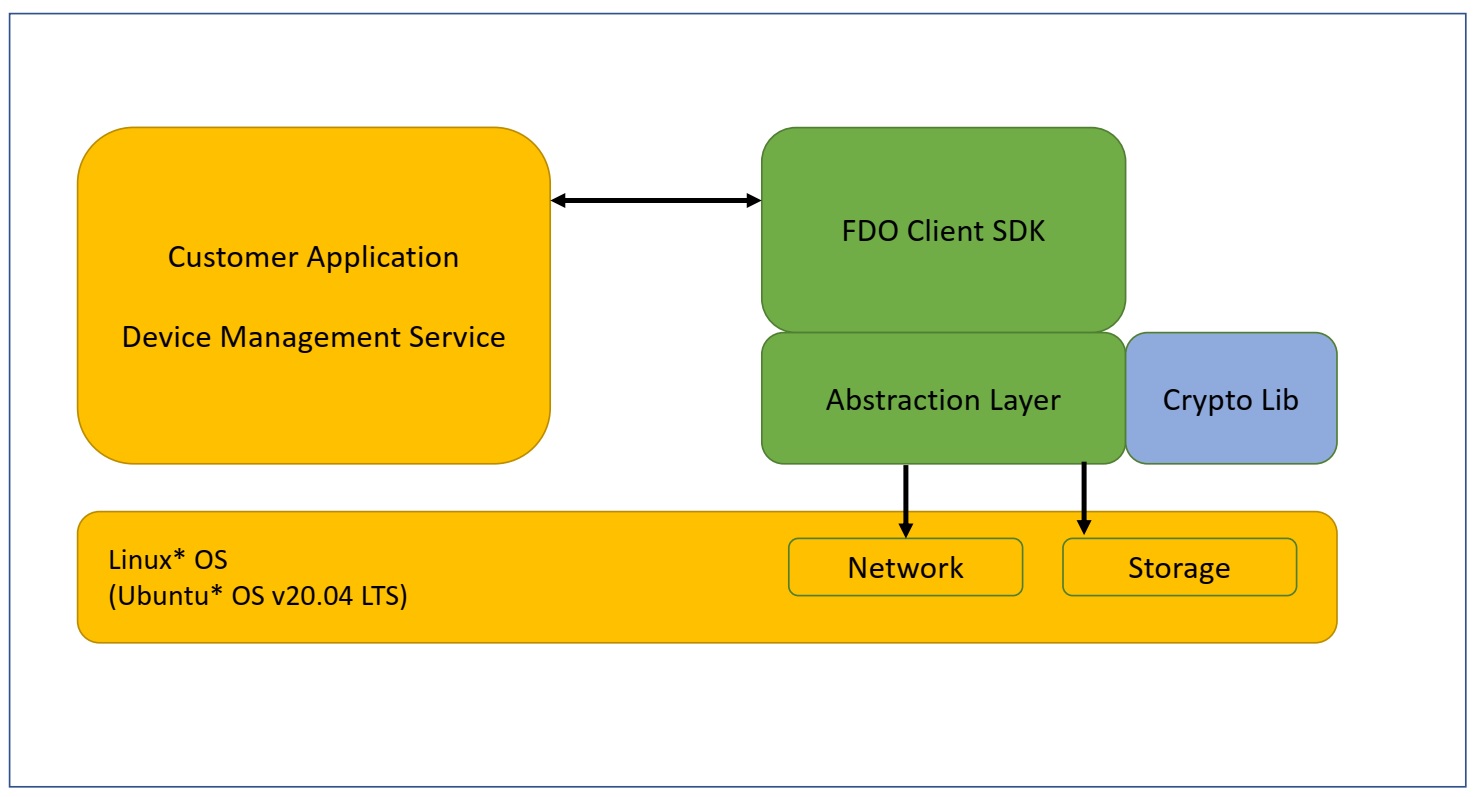
The FIDO Device Onboard Client SDK is a portable implementation of the FIDO Device Onboard (FDO) protocol state machines, cryptographic operations, and associated components. While the Client SDK was developed and tested on the Linux* OS, the core components of the SDK are isolated from OS-specific components via an abstraction layer. Well-known open-source implementations of cryptographic libraries are used for cryptographic operations.
In addition, the Client SDK will be ported to the following Arm* platforms in future releases:
- Nucleo development board (NUCLEO-F429ZI) running STM32F429ZI ARM Cortex-M4 MCU over Mbed* OS.
- NUCLEO-F767ZI development board running STM32F767ZI Arm Cortex-M7 MCU over Mbed* OS.
- WaRP7 development board running i.MX 7 series Arm Cortex-A7 MPU over Mbed Linux.
The Client SDK is a reference implementation that can be used to onboard a device and then give control to the device application or IOT Platform Service. “Onboarding” means the process by which a device establishes its first trusted connection with an IOT Platform Service.
Linux provides an easy-to-use development environment for SDK development, debug, and validation. When the SDK is ported to a particular environment, the abstraction layer will be ported to the target environment and real-time operating system (RTOS) (or bare metal). If the target environment supports hardware-accelerated cryptography, the cryptography interfaces will also be ported. If the target environment does not support cryptographic acceleration, the software cryptography libraries used by the SDK will need to be ported. The core SDK can be recompiled in the target environment with no change.
Note
The hardware abstraction layer (HAL) implementation provided in this release is for reference only and not intended for production. It does not provide the level of security required by industry standards for a fully secure production environment.
Terminology
Refer to the FIDO Device Onboard Reference page.
Reference Documents
Refer to the FIDO Device Onboard Reference page.
Client SDK Overview
Like any SDK, the Client SDK is expected to be embedded within a custom implementation that provides overall device functionality while using the SDK to perform FDO-based device onboarding. The SDK will be statically linked to an application that invokes SDK APIs to trigger onboarding functionality. This implementation is referred to as the ‘Application’ in this document.
Figure 1. FDO Client Block Diagram
Note
FDO is an acronym for FIDO Device Onboard.
Before initiating the FIDO Device Onboard functionality, the Application must first initialize the SDK. After initializing the SDK, the Application can initiate the onboarding by calling the fdo_sdk_run()API.
The SDK maintains persistent data such as configuration and state information that are used to track the onboarding state and store credentials, among others. This information is stored in the SDK Configuration file that persists across reboots.
Threading Model
The FDO Client SDK is single threaded and the APIs are non-reentrant and blocking. SDK code executes in the context of the calling application thread and will make OS calls via the abstraction layer for storage and networking services within the context of this thread. OS service such as storage and network are assumed to be blocking.
During the execution of the onboarding protocol, the SDK receives data from the Owner Server that must be passed back to application modules (Pre-Service & Owner ServiceInfo).This is achieved via module-specific callback functions that are registered during the SDK initialization.
These callback functions are also called within the context of the application thread that entered the SDK via one of the SDK’s APIs (fdo_sdk_run). The application must not invoke an SDK API from within the callback – SDK flows have been designed such that this is not required.
In addition to module specific callbacks, the SDK requires an additional callback that is used to inform the Application of events occurring during long-running activities, such as network connection retries, as well as errors, such as network connection drop.
Networking
It is assumed that the machine on which the SDK runs has access to the network. The SDK uses standard POSIX sockets interface to connect to external back-end Rendezvous and Owner Servers. The SDK uses the OpenSSL* toolkit for SSL support.
The SDK will initiate connections to the following external ports, which must not be blocked by a firewall:
- 8039: The SDK connects to the FDO Manufacturer Server on this port.
- 8040: The SDK connects to the FDO Rendezvous Server on this port.
- 8042: The SDK connects to the FDO Owner Server on this port.
For details on the Manufacturer Server, Rendezvous Server, and Owner Server refer to the Reference Documents.
Device-Specific Modules
FDO is a generic mechanism of establishing trust between a device and the final owner’s cloud-based IOT Platform Service (known as the Owner Service). Once this trust is established, the Owner Service must perform the following actions:
- Setup the device for final operation. This requires configuration of device specific operational parameters. This is determined by the device being onboarded, for example, it is device specific.
- Full integration into the organization’s IOT Platform Service. This is specific to the IOT Platform Service being used.
Since FDO cannot define these steps for all devices and IOT Platforms, it provides a flexible method to allow these operations to be carried out in a secure manner using Modules.
Modules are defined by the device manufacturer (ODM) and are pieces of code that have a specific name and perform a specific function. Firmware update, key provisioning, and Wi-Fi* network setup are some examples of common functionality that could be provided by modules.
A module must be able to report information [called the Device ServiceInfo], to IOT Platform, and/or accept configuration information [called the Owner ServiceInfo], from the Owner Service. A module must also be able to publish details of what information it will report as Device ServiceInfo and/or what information it will accept as Owner ServiceInfo. This is done in the form of key-value pairs. The key identifies a parameter and the value provides the value of the parameter.
A module will publish its interface in the form of Device and Owner ServiceInfo Keys (ServiceInfoKey) with associated valid values (ServiceInfoVal). The Owner Service is expected to be aware of all devices it will onboard and associated Device and Owner ServiceInfo interfaces.
Note
In this release, a module can only be integrated for processing Owner ServiceInfo. Support for integrating Device ServiceInfo modules into the Client SDK will be added in future releases.
Note
The expectation is that over time, much like reusable libraries, modules providing specific functionality such as firmware updates or key provisioning will become standardized in terms of their capabilities and interfaces. Device manufactures will simply port the modules and include these libraries to their device implementation. A similar development is expected to occur on the Owner Server side where standard libraries will be developed to interact with the device module and included in the Owner Server implementation.
When a device is onboarded, a secure channel is established between the device and Owner Server after the device has authenticated the Owner Server and vice-versa (during the TO2 protocol). At this point, the Owner Server can query information from the device (Device ServiceInfo) and send down configuration information to the device (Owner ServiceInfo). The secure channel uses encryption and integrity protection to secure Device ServiceInfo/Owner ServiceInfo data in transit from/to the device.
The Device ServiceInfo must always send 'devmod' module as the very first module, containing a list of supported modules along with basic capabilities expected of the module. The following section details the interactions between the Application, Client SDK and Device-specific Modules.
Integrated Operational Flows
This SDK release requires all software components to be linked together into a single binary image and execute at the same privilege level. While some systems might include overlays and Trusted Execution Environments, these are not considered for this version.
Figure 2. Integrated Image and Execution Flow
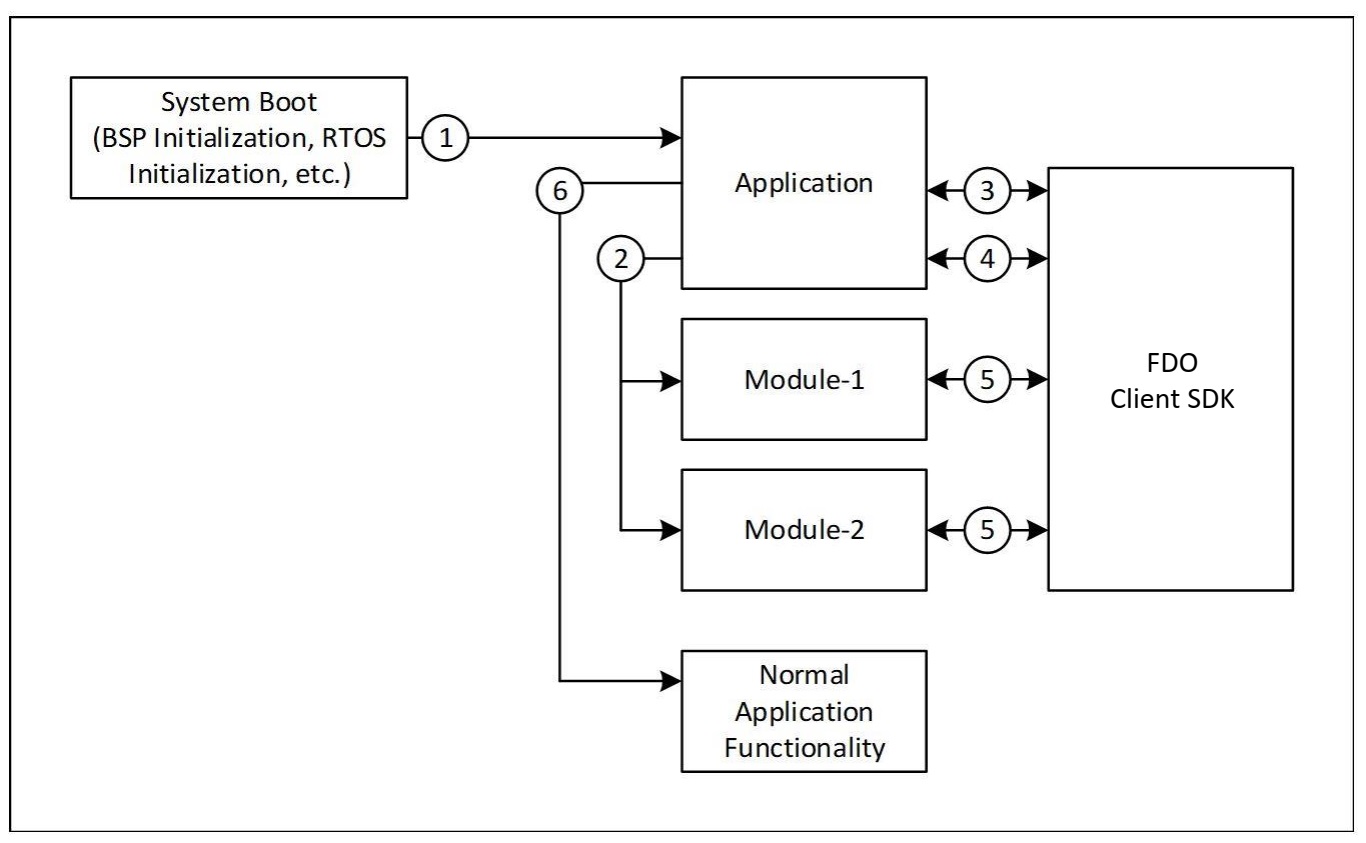
The integrated image and execution flows from system boot are shown above and each step is described below:
-
On reset, the Board Support Package (BSP) and RTOS initialize the hardware and pass the control to the Application. On Linux* systems, this is the normal OS boot flow and is complete by the time the Application executes.
-
The Application initializes all FDO modules if required. The Application also initializes the SDK by calling the
fdo_sdk_init()API and registers each module with the SDK by passing the module’s name and callback address to the SDK (in thefdo_sdk_service_info_modulestructure). - The Application checks if FDO onboarding has been completed by calling the
fdo_sdk_get_status()API. If the statusFDO_SDK_STATE_IDLEis returned, onboarding has been completed and the Application goes to step 6. If not, the Application goes to step 4. - The Application initiates FDO onboarding by calling the
fdo_sdk_run()API. This call returns either a successful completion of onboarding or an error. If an error occurs, the Application will reset the device and retry the sequence, with some delay. On successful completion of onboarding, the Application goes to step 6. - During the onboarding process, the SDK will call registered modules during the Service Info stage of the protocol. This is done by calling the registered module callback. Details of this interaction are provided in the Figure 3. The onboarding process will succeed only if all module interactions at this stage are successful.
- The Application has successfully completed onboarding and continues normal operation of the device.
The Application continues operating until the system is powered off or reset. On System restart, the preceding steps are re-executed.
FDO Module Flows
As mentioned in Device Specific Modules section, three types of information exchange occur between each module and the Owner Service:
- Device ServiceInfo
- Owner ServiceInfo
Each of these is described as follows:
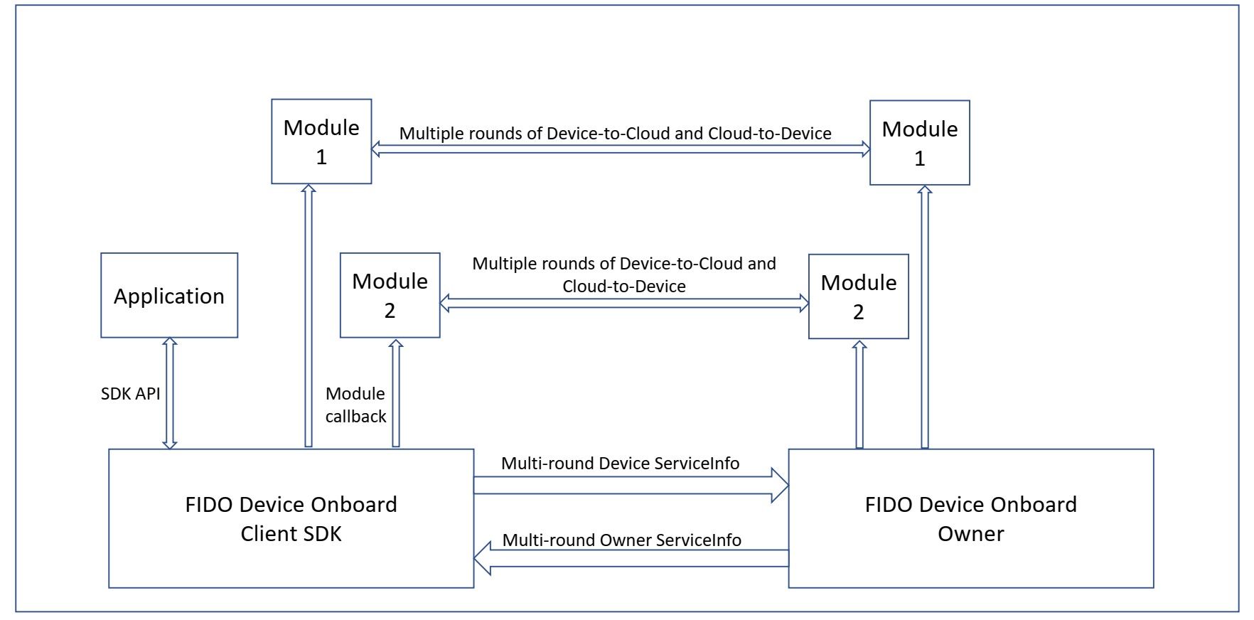
Figure 3. Service Info Exchanges between Device and Owner Server
Module Initialization
For each registered module, the SDK initializes the module by calling its callback with the FDO_SI_START type. The module is expected to prepare to receive PSI, Device ServiceInfo, and Owner ServiceInfo calls after initialization.
If an error occurs after a module has been initialized, during the remainder of TO2 protocol execution and the Application is restarted, the SDK will again call this API to initialize each registered module. The module must be prepared for multiple such calls due to the SDK’s retry-based approach to error recovery.
Device ServiceInfo
This is the information that make the Owner aware of the supported Owner ServiceInfo modules along with other information that aids in proper configuration of the Device. The module needs to determine in advance how many Device ServiceInfo key-value pairs it needs to send to the Owner Service.
The Device initally sends the 'devmod' module in the first round. Other module is sent to the Owner in subsequent rounds. As mentioned previously, only one Device ServiceInfo module is supported currently, i.e, devmod module, which is configured statically in app_initialize(). All but one parameters are configured in the same method, except Device ServiceInfo Key devmod:modules that is configured in fdo_serviceinfo_modules_list_write(). The total number of supported Owner ServiceInfo modules and their names must be updated in the above mentioned methods. Support for handling multiple Device ServiceInfo modules will be added in future releases.
Note that Device ServiceInfo is one way – from device to Owner Server. The Owner Server cannot respond to any Device ServiceInfo message during this phase.
Owner ServiceInfo
Owner ServiceInfo follows Device ServiceInfo. Unlike Device ServiceInfo, neither the SDK nor the module can determine in advance how many Owner ServiceInfo key-values they are going to receive. On receiving an Owner ServiceInfo, the SDK locates the module and invokes its callback with the FDO_SI_SET_OSI type.
The Owner is supposed to send module activation message, that is it sends active key with value true for a particular module, prior to sending the Owner ServiceInfo for that module. When the SDK receives the same, it activates that particular module and passes on the subsequent ServiceInfo key-values to that module. If the SDK receives ServiceInfo for a module that is, either not supported, or, is not currently active, it returns without throwing any error, without invoking the callback method. Optionally, the Owner Server could send a deactivation message to a module, that is it sends active key with value false for a particular module if it is not planning to use the module.
Received key-values are passed to the module in the module_message and fdor callback parameter fields. The internal buffer of fdor contains the entire message as received in TO2.OwnerServiceInfo (Type 69) with the current position set to the received Owner ServiceInfo value (ServiceInfoVal), while the Owner ServiceInfo key (ServiceInfoKey) is provided in module_message. The module must read the value from fdor_t, process it as per the key, and advance the fdor_t internal buffer to the next valid CBOR entry (currently being done internally in few methods). The module must treat the received fdor_t as a read-only structure, and must never modify it, excpet advancing to the next CBOR entry. It is assumed that the module knows how to interpret the value for a particular key based on the key.
The module is expected to process the key-value pair and return a result indicating if the operation was successful or failed. The module may return FDO_SI_CONTENT_ERROR or FDO_SI_INTERNAL_ERROR to differentiate between invalid value contents or a module run-time error. This information is reported to the Owner Server. The module must return FDO_SI_SUCCESS on successful completion.
Note that Owner ServiceInfo is one way – from Owner Server to the device. Apart from indicating failure, the device cannot respond to an Owner ServiceInfo message.
Module Completion
When all ServiceInfo rounds of all modules have completed successfully, the SDK calls each module’s callback with the FDO_SI_END type. All other callback parameters are NULL. Modules can commit configuration information at this point if not already done so.
The SDK will not call into the module after this. The SDK will ignore the return value of this callback since no further failure is expected at this point.
Module Errors
If an error occurs during the ServiceInfo phase, the TO2 protocol is considered to have failed and will be aborted. The Application will need to retry onboarding later. A failure could occur for multiple reasons including failure of device/server interaction, failure of signature or hash verification, malformed messages and if a module returns a failure while processing a PSI, Device ServiceInfo, or Owner ServiceInfo command/request.
On failure, all modules must clean up internal state and discard any configuration information they might have got from the Owner Server. Conversely, the Owner Server will also discard all data it might have received from modules.
When all ServiceInfo rounds of all modules have completed successfully, the SDK calls each module’s callback with the FDO_SI_FAILURE type. All other callback parameters are NULL. Modules must discard all information received via Owner ServiceInfo commands until this point. If operations have been performed, or data already committed, they should be undone to return the system to it intial state.
The SDK will not call into the module after this. The SDK will ignore the return value of this callback since no further failure is expected at this point.
Run the Client SDK
The Client SDK includes a binary package, intended to get you started quickly and a source package. For details on downloading the packages, refer to the Get Started Guide.
Prerequisites
The requirements for the computer that you will run Client SDK on are as follows:
Table 1. Prerequisites
| Software | · Linux* Ubuntu* 20.04 using OpenSSL* 1.1.1k . Download FDO PRI Components-Samples 0.5-rel (for running test servers) from https://github.com/secure-device-onboard/pri-fidoiot. |
| Safestring library | Safestring library v1.0.0 · Download safestringlib from https://github.com/intel/safestringlib · cd safestringlib · mkdir obj · make · The library file libsafestring.a will be created after make. |
| TinyCBOR library | TinyCBOR library v0.5.3 · Download TinyCBOR from https://github.com/intel/tinycbor · cd tinycbor · make |
Get the Device Private Key (ECDSA based)
The SDK requires a device Private Key as input for device attestation process (to prove itself to Rendezvous or Owner Server during TO1 or TO2 protocol). The key could be based on ECDSA (on curve P-256/P-384) based on the device attestation method being used on the field. This key must be stored in a specific file and is read by the SDK on startup.
For ECDSA (P-256) based device-attestation method:
In case of ECDSA, place the ECDSA P-256 private Key with the name ecdsa256privkey.dat in the following location:
data/ecdsa256privkey.dat
For ECDSA (P-384) based device-attestation method:
For ECDSA384, place the ECDSA P-384 private Key with the name ecdsa384privkey.dat in the following
location: data/ecdsa384privkey.data
Run the FDO Client SDK Onboarding Demo
Refer to Client SDK README for detailed steps on setting up FDO Client SDK and FDO PRI Manufacturer, Rendezvous and Owner and running the demo.
Custom Pluggable Modules
As part of the onboard protocol, the Client SDK supports custom pluggable modules. OEMs can develop their desired functionality by following the module protocol. This module functionality will be called during the onboard protocol.
A sample device module, fdo_sys has been developed as per specification, and is available for reference.
fdo_sys device module is intended to collect the data (typically files and scripts) sent from the FDO PRI Owner to the FDO Client SDK, process, and execute the data in some meaningful way.
To use fdo_sys device module, follow these steps:
To use the sample device module fdo_sys :
- Build Client SDK either in release or debug mode using MODULES=true flag.
$ cd client-sdk/
$ cmake -DMODULES=true .
$ make -j(nproc)
The binary would be created either in build/linux/debug or build/linux/release folder. Copy them to the root folder before proceeding with the next steps.
- Run the FDO Linux* device for Device Initialization (DI) protocol:
$ ./linux-client
--------DI successful--------
- Run the FDO Linux* device for Transfer of Ownership (TO1/TO2) protocol (it is assumed that ownership voucher is correctly extended and TO0 is successfully completed prior to this step):
$ ./linux-client

--------TO2 successful--------
@@@@@@@@@@@@@@@@@@@@@@@@@@@@@@@@@@@
@FIDO Device Onboarding Complete@
@@@@@@@@@@@@@@@@@@@@@@@@@@@@@@@@@@@
Known Issues and Limitations
The following are the known issues:
• The HAL implementation provided in this release is for reference only and not intended for production. It does not provide the level of security required by industry standards for a fully secure production environment.
• ‘fdo_sys’ module source within 'device_modules' folder is an example code demonstrating FDO device module implementation for reference purpose only. The executable script must only contain alpha-numeric characters and underscore (_) in their names, with extensions .py and .sh. This code is not written following secure production level coding and checks. This sample code must not to be used as it is.
The following are the known limitations:
• The ARM platforms, namely ARM Cortex M4, M7, and A7 devices, as well as mbedTLS and SE crypto operations, are not supported in this release.